Mycila::PID — Detailed Guide
This document describes the Mycila::PID controller provided by MycilaUtilities. It consolidates header documentation (src/MycilaPID.h) and adds examples and best practices.
- Overview
- Key API
- Modes explained
- Time sampling
- Reverse mode
- Feed-forward
- Output limits and anti-windup
- Lifecycle patterns
- Quick start example
- JSON integration example
- Best practices
- Troubleshooting
- License
- PIDSimulator example — Solar diversion demo
Overview
Mycila::PID is a compact, efficient, and flexible PID controller designed for embedded applications (Arduino/ESP32). It supports:
- Proportional/Derivative modes: compute terms from either error (setpoint − input) or input deltas
- Integral correction mode (anti-windup): clamp integral term to output limits or disable correction
- Optional output limits to bound the controller output
- Reverse action to invert controller direction (e.g., cooling vs heating)
- Optional time-sampling to scale Ki/Kd by elapsed time between
compute()calls - Lifecycle helpers:
reset(),pause(),resume()(with optional initial output) - Introspection getters for last input/output and P/I/D terms
- Optional JSON serialization (enable by defining
MYCILA_JSON_SUPPORTbefore including the header)
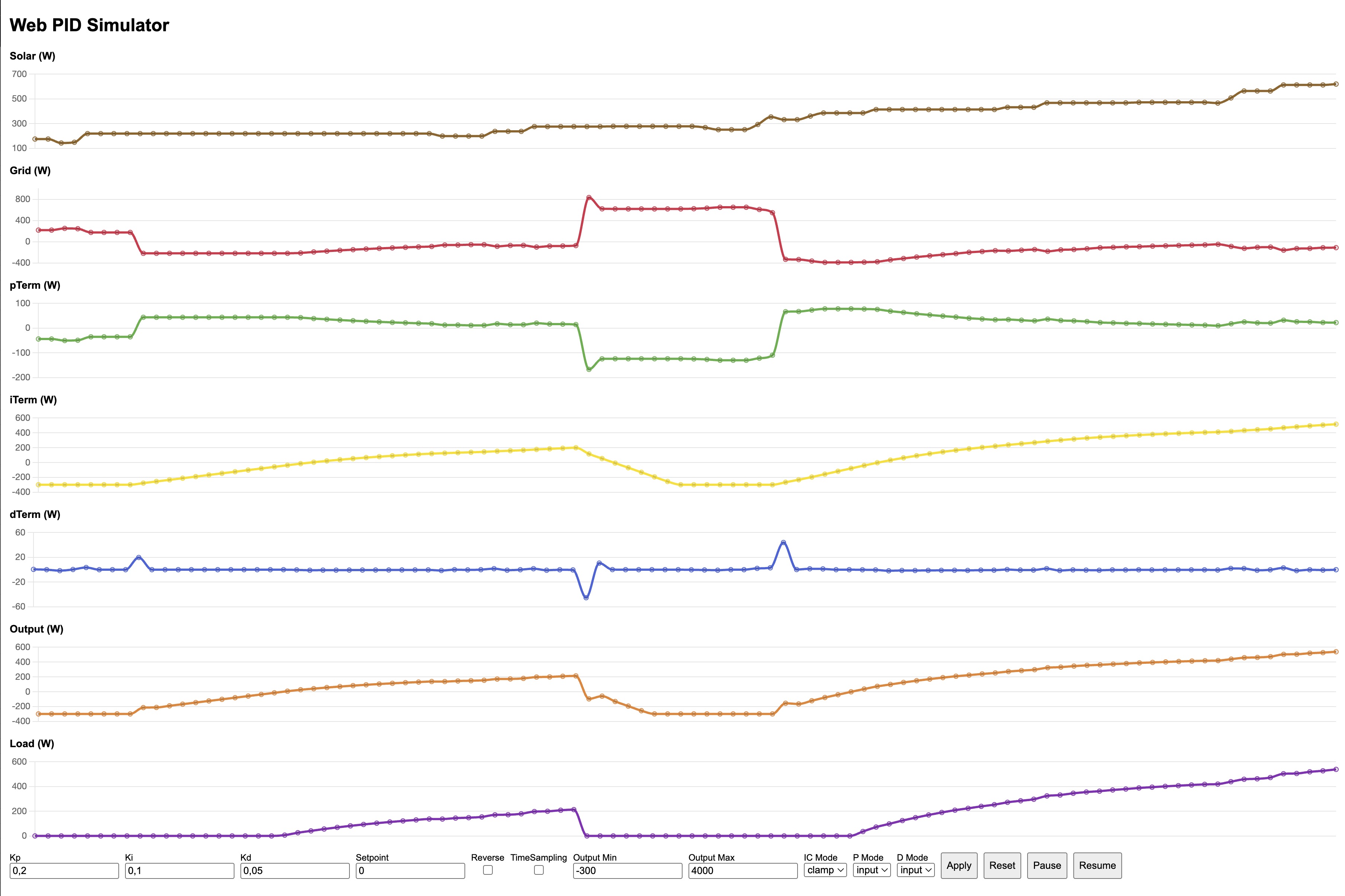
PID Simulator available in examples/PIDSimulator (video link)
Key API
Header: #include <MycilaPID.h>
-
Setpoint and tunings
void setSetpoint(float sp)void setKp(float kp),void setKi(float ki),void setKd(float kd)void setTunings(float kp, float ki, float kd)(sets all at once)void setFeedForward(float ff)— set the feed-forward term (added to output)
-
Modes
- Proportional:
setProportionalMode(PID::ProportionalMode::{ON_ERROR|ON_INPUT}) - Integral correction:
setIntegralCorrectionMode(PID::IntegralCorrectionMode::{OFF|CLAMP})
- Proportional:
-
Direction and timing
void setReverse(bool reverse)— invert control actionvoid setTimeSampling(bool enabled)— when enabled, Ki and Kd are scaled using elapsed time between calls
-
Output limits and lifecycle
void setOutputLimits(float min, float max)— also clamps I-term and last output to limitsvoid unsetOutputLimits()— disables limits (and any clamp-based anti-windup)void reset(float initialOutput = NAN)— clear state; when initial output is provided, initializes I-term and output to that valuevoid pause()andvoid resume()/void resume(float initialOutput)
-
Compute and state
float compute(float input)— returns a new output using current settings- State getters:
getInput(),getOutput(),getSetpoint()getPTerm(),getITerm(),getDTerm(),getFeedForward()getKp(),getKi(),getKd()getOutputMin(),getOutputMax()getProportionalMode(),getIntegralCorrectionMode()isEnabled(),isReverse(),isTimeSampling()
-
JSON export (optional)
- Define
MYCILA_JSON_SUPPORTbefore including the header to enablevoid toJson(JsonObject&) const.
- Define
Modes explained
-
Proportional
ON_ERROR: P = Kp * (setpoint − input) — classic behaviorON_INPUT: P is reduced using input delta:P -= Kp * dInput(good for softer response near setpoint)
-
Derivative
ON_ERROR: D = Kd * dErrorON_INPUT: D = −Kd * dInput (derivative on measurement)
-
Integral correction
OFF: no clamp (fastest but can wind up)CLAMP: I-term is clamped within output limits to reduce windup (requires limits)
Time sampling
When setTimeSampling(true) is enabled:
Kiis scaled by elapsed timedt(seconds)Kdis scaled by1/dtThis makes the controller resilient to variable loop timing.
The controller measures dt internally using micros() and updates on every compute() call.
Reverse mode
When reverse is enabled, the controller inverts the signs of Kp/Ki/Kd internally, effectively reversing the direction of the control action (useful for cooling systems or inverted actuators).
Feed-forward
Feed-forward allows you to add a known expected output value directly to the PID output, improving response time and reducing steady-state error when you have partial knowledge of the system.
- Use
setFeedForward(float value)to add a constant term to the output - The feed-forward term is added after computing P + I + D:
output = P + I + D + FeedForward - Useful for precompensating known disturbances or expected output values based on setpoint or other system states
- Example: if you know a certain setpoint typically requires ~50% output, set feed-forward to 50 to reduce the PID’s workload
When to use feed-forward:
- You have a model or empirical relationship between setpoint and required output
- You want faster response to setpoint changes
- You want to reduce overshoot by giving the controller a head start
Output limits and anti-windup
- Use
setOutputLimits(min, max)to bound outputs (and I-term when integral correction mode is CLAMP). - Use
unsetOutputLimits()to remove limits and disable clamp-based anti-windup. - After changing limits, the last output and I-term are clamped accordingly.
Lifecycle patterns
-
Resetting on mode or setpoint changes
- After a large setpoint or mode change, consider calling
reset()to clear historical terms - Alternatively, use
reset(initialOutput)to start near an expected output and avoid big bumps
- After a large setpoint or mode change, consider calling
-
Pause/Resume
pause()freezes the output (compute() returns the last output)resume()continues normal compute;resume(initialOutput)resets to a known output and resumes
Quick start example
#include <MycilaPID.h>

Mycila::PID pid;

void setup() {
  pid.setSetpoint(0.0f);
  pid.setTunings(0.1f, 0.2f, 0.05f);
  pid.setOutputLimits(-300.0f, 4000.0f);
  pid.setIntegralCorrectionMode(Mycila::PID::IntegralCorrectionMode::CLAMP);
  pid.setProportionalMode(Mycila::PID::ProportionalMode::ON_INPUT);
  pid.setTimeSampling(false);
  pid.setReverse(false);

  // Optional: set feed-forward if you know expected baseline output
  // pid.setFeedForward(50.0f);
}

void loop() {
  float measured = readSensor();
  float out = pid.compute(measured);
  applyActuator(out);
}
JSON integration example
#define MYCILA_JSON_SUPPORT
#include <ArduinoJson.h>
#include <MycilaPID.h>

Mycila::PID pid;

void dumpPid(JsonDocument& doc) {
  JsonObject obj = doc.to<JsonObject>();
  pid.toJson(obj);
}
Best practices
- Always set sensible output limits for real actuators; combine with
CLAMPto reduce overshoot - Use time sampling for non-constant loop times
- Consider reverse mode for cooling or inverted processes
- Reset after major setpoint or mode changes; use
reset(initialOutput)to reduce initial bumps - Tune Kp/Ki/Kd conservatively; start with small Ki/Kd and increase gradually
Troubleshooting
- Oscillation or overshoot
- Reduce Kp or Ki; ensure output limits are set and CLAMP is enabled
- Slow response
- Increase Kp slightly or adjust Ki; try ON_INPUT modes to soften overshoot near setpoint
- No effect
- Check wiring to actuator, verify output limits, ensure
compute()is called frequently, and PID is not paused
- Check wiring to actuator, verify output limits, ensure
License
MIT (see project LICENSE)
PIDSimulator example — Solar diversion demo
The PIDSimulator example (examples/PIDSimulator/PIDSimulator.ino) showcases Mycila::PID in a simulated solar-diversion scenario.
What it simulates
- Solar production (
solar) fluctuating over time - Grid value (
grid) used as the PID input - PID internal terms:
pTerm,iTerm,dTerm - Controller
outputand a simulatedload(diverted power)
Web UI and controls
- The sketch starts an ESP32 access point named
esp-captive - Browse to http://192.168.4.1/ to open the single-page UI
- Live charts update via WebSocket with the following series: Solar, Grid (PID input), pTerm, iTerm, dTerm, Output, Load
- Controls available: Kp, Ki, Kd, Setpoint, Reverse, TimeSampling, Output limits, P/D/IC modes, Pause/Resume/Reset
- You can click a chart title to show/hide that chart
How to run
- Build and flash
examples/PIDSimulator/PIDSimulator.inoto an ESP32 - Connect to the
esp-captiveWi‑Fi access point - Open http://192.168.4.1/
- Tune parameters and observe how Solar/Grid/Output/Load evolve in real time
Tip: Start with conservative gains (e.g., small Ki/Kd) and enable output limits with CLAMP integral correction to reduce overshoot.
 |
 |
Web version
An online version is available now at https://mathieu.carbou.me/MycilaUtilities/simulator/