MycilaPulseAnalyzer
ESP32 / Arduino Library to analyze pulses from a Zero-Cross Detection circuit and manage the Zero-Cross pulse.
- Features
- Supported ZCD Circuits
- Usage
- IRAM Safety
- Zero-Cross event shift
- Oscilloscope Views
- Use-Case: Thyristor TRIAC Control
- Use-Case: Know when the AC voltage is positive or negative
- Readings
Features
- Detect Zero-Cross pulse
- Ability to shift the Zero-Cross event (
MYCILA_PULSE_ZC_SHIFT_US) - Filter spurious Zero-Cross events (noise due to voltage detection)
- Online / Offline detection
- Uses only 2 timers
- IRAM safe and supports concurrent flash operations!
- Callbacks for:
- Zero-Cross,
- Rising Signal
- Falling Signal
- Signal Change (BM1Z102FJ)
- Measurements:
- Period
- Minimum Period
- Maximum Period
- Frequency
- Pulse Width
- Minimum Pulse Width
- Maximum Pulse Width
This library is used in YaSolR Solar Router to detect Zero-Cross pulse and control the Thyristor / TRIAC with many supported ZCD modules.
Supported ZCD Circuits
-
Square short pulse (e.g. Zero-Cross Detector from Daniel)
-
Slope pulse (e.g. Robodyn ZCD)
-
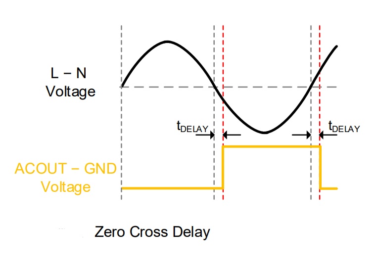
High precision pulse matching AC wave +/- components based on BM1Z102FJ chip (e.g. AC VOLTAGE ZERO CROSS DETECTOR - note that this one needs an additional optocoupler like TLP2630 or 6N136)
-
JSY-MK-194G Zero-Cross Pulse where the pulse length equals the period length
More hardware are supported, as long as they fall into one of these categories above.
 |
  |
 |
Usage
Mycila::PulseAnalyzer pulseAnalyzer;

static void ARDUINO_ISR_ATTR onEdge(Mycila::PulseAnalyzer::Event e, void* arg) {
  if (e == Mycila::PulseAnalyzer::Event::SIGNAL_RISING || e == Mycila::PulseAnalyzer::Event::SIGNAL_FALLING) {
    digitalWrite(PIN_OUTPUT, HIGH);
    delayMicroseconds(OUTPUT_WIDTH_US);
    digitalWrite(PIN_OUTPUT, LOW);
  }
}

static void ARDUINO_ISR_ATTR onZeroCross(void* arg) {
  digitalWrite(PIN_OUTPUT, HIGH);
  delayMicroseconds(OUTPUT_WIDTH_US);
  digitalWrite(PIN_OUTPUT, LOW);
}

void setup() {
  Serial.begin(115200);
  while (!Serial)
    continue;

  pinMode(PIN_OUTPUT, OUTPUT);

  pulseAnalyzer.onEdge(onEdge);
  pulseAnalyzer.onZeroCross(onZeroCross);

  pulseAnalyzer.begin(35);
}
Output:
{"state":0,"period":9994,"period_min":9975,"period_max":10014,"frequency":100.0600357,"width":1168,"width_min":1154,"width_max":1182}
{"state":0,"period":9993,"period_min":9976,"period_max":10018,"frequency":100.0700455,"width":1166,"width_min":1154,"width_max":1180}
IRAM Safety
You can run the app with:
-D CONFIG_ARDUINO_ISR_IRAM=1
-D CONFIG_GPTIMER_ISR_HANDLER_IN_IRAM=1
-D CONFIG_GPTIMER_CTRL_FUNC_IN_IRAM=1
-D CONFIG_GPTIMER_ISR_IRAM_SAFE=1
-D CONFIG_GPIO_CTRL_FUNC_IN_IRAM=1
This will improve interrupt reliability (they will continue working even during flash operation).
MycilaPulse makes use of inline function of HAL layer and ARDUINO_ISR_ATTR to ensure that the interrupt handlers are in IRAM.
You can look at teh examples in the project to see how to use this library with IRAM safety.
Zero-Cross event shift
Compile flag -D MYCILA_PULSE_ZC_SHIFT_US is used to control the shift of the Zero-Cross event.
By default, the value is set to -150 us, which means that the Zero-Cross event is shifted by - 150 us from the middle of the pulse (or start of the front edge in the case of the BM1Z102FJ chip).
You can also use the getters and setters:
pulseAnalyzer.setZeroCrossEventShift(-100);
pulseAnalyzer.setZeroCrossEventShift(-150); // default value
For the JSY-MK-194
MYCILA_JSY_194_SIGNAL_SHIFT_US is used to compensate the signal shift of the JSY-MK-194, because the JSY will detect the Zero-Cross event ~ 100 us after the actual zero.
The JSY-MK-194T detection happens after 1000 us.
You can also use the getters and setters:
pulseAnalyzer.setJSY194SignalShift(-100); // For JSY-MK-194G (default value)
pulseAnalyzer.setJSY194SignalShift(-1000); // For JSY-MK-194T
Oscilloscope Views
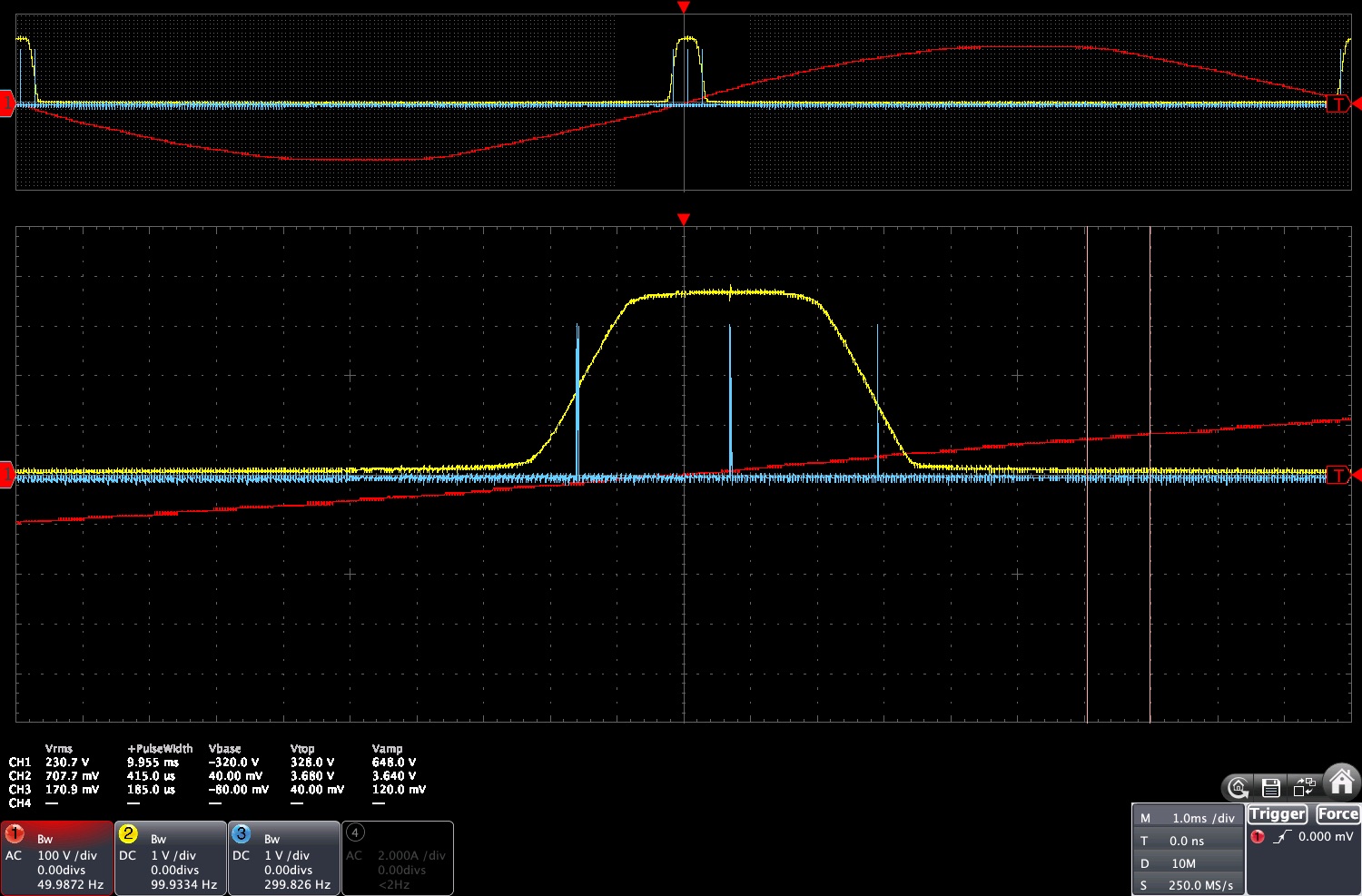
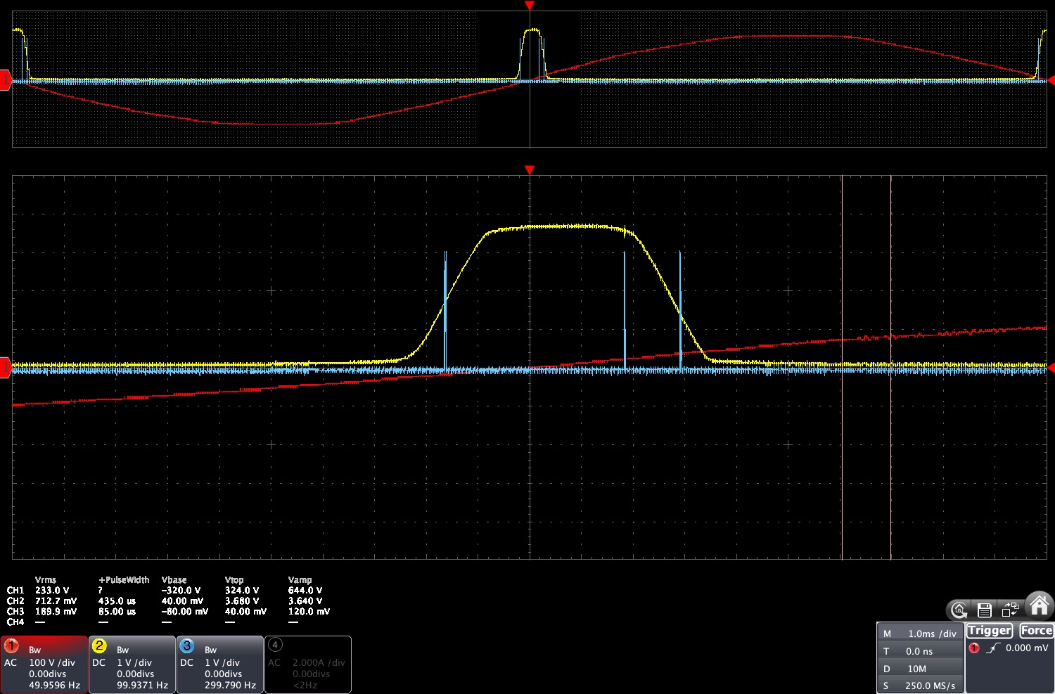
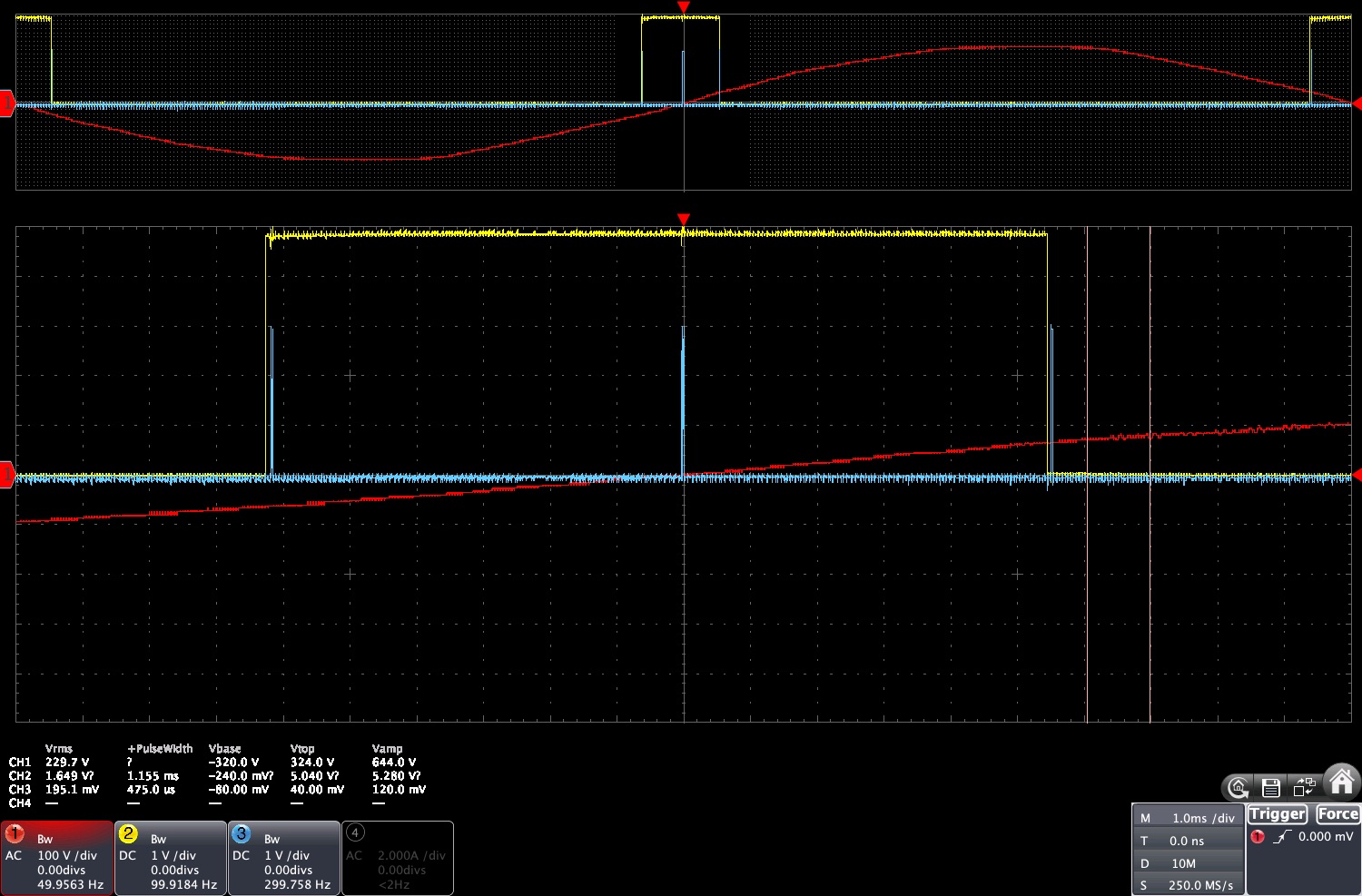
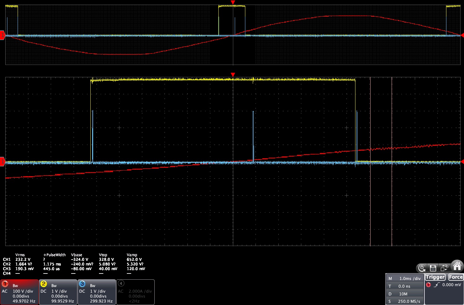
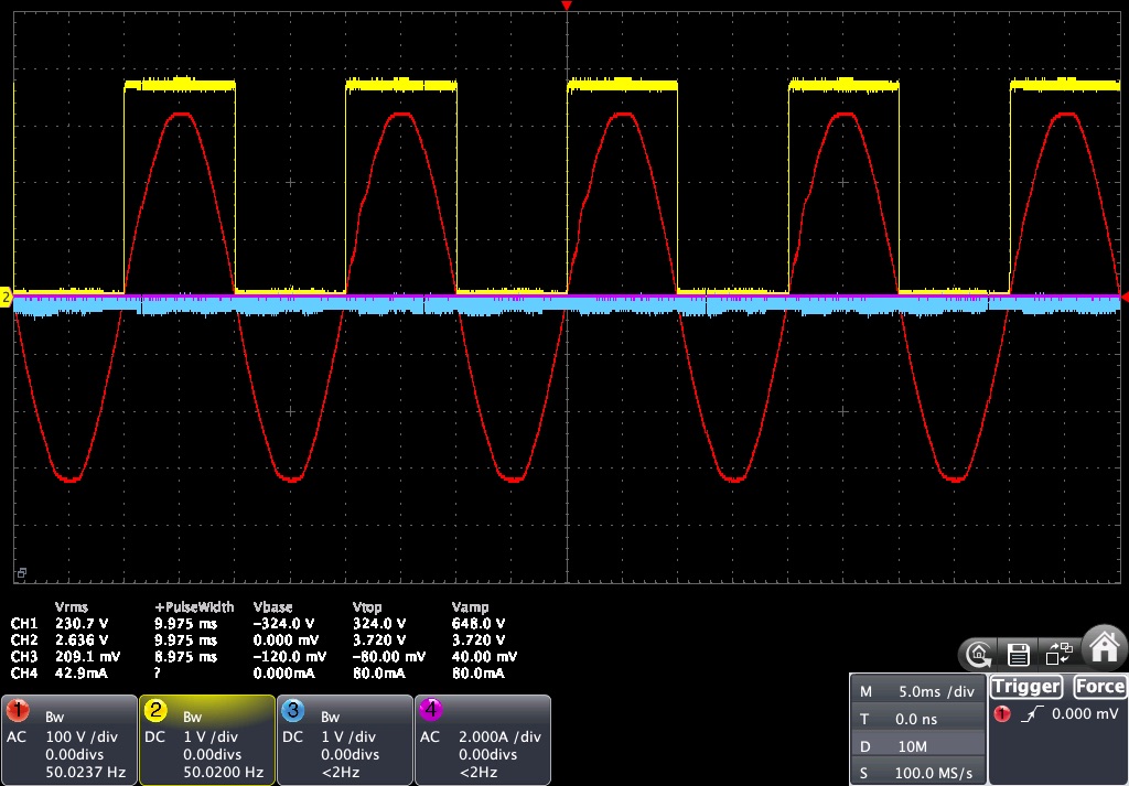
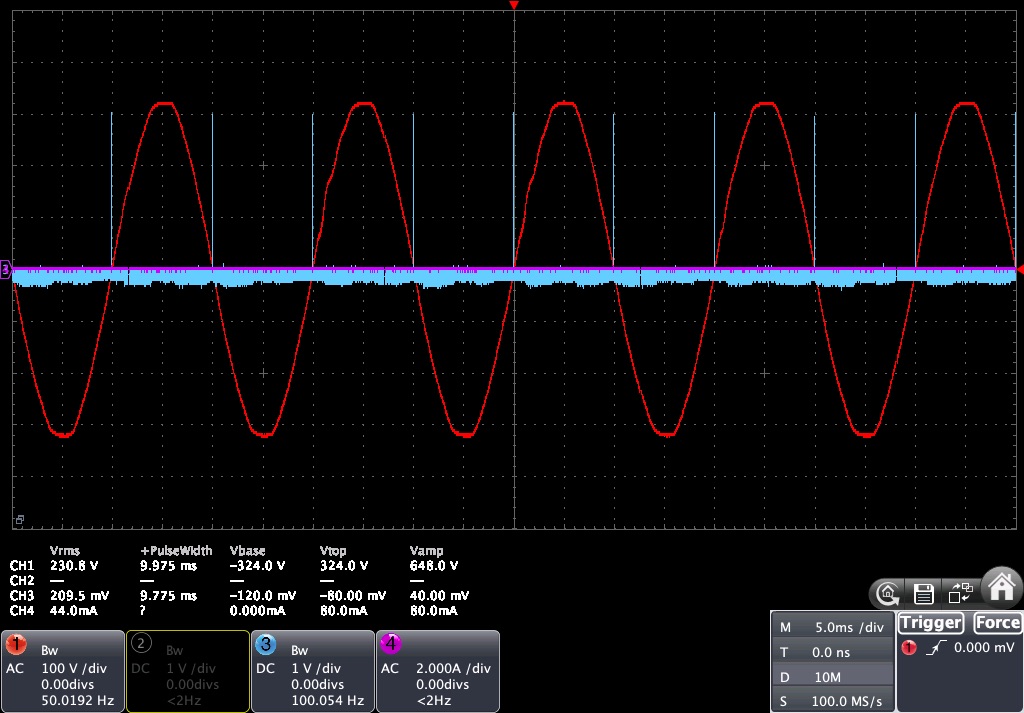
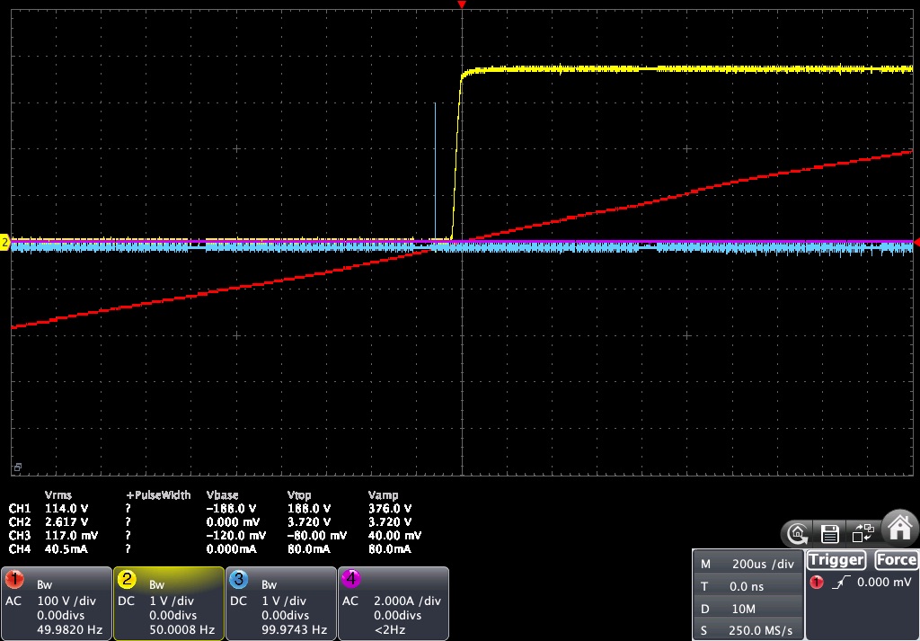
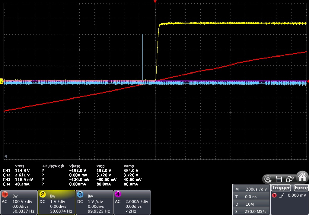
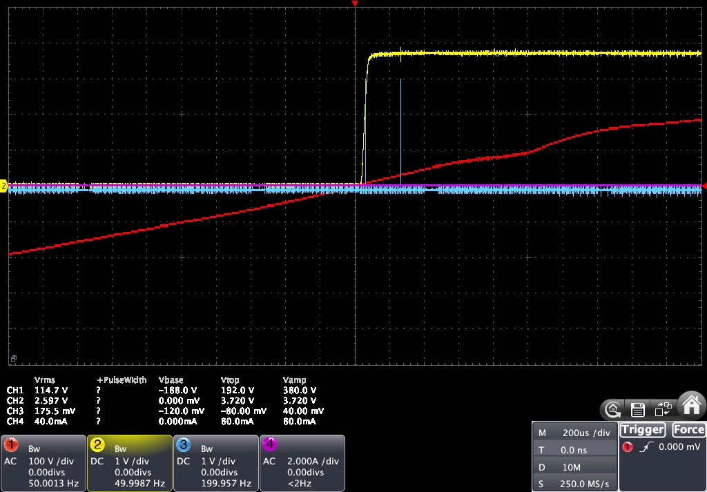
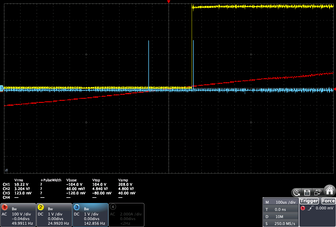
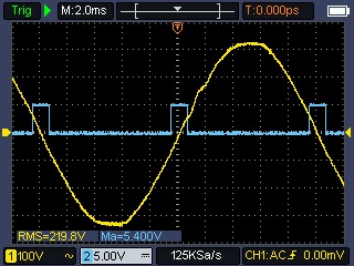
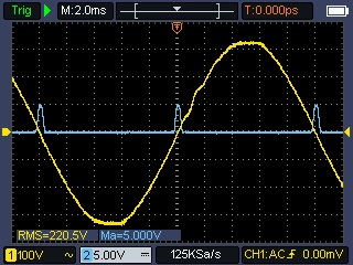
Here are below some oscilloscope views of 2 ZCD behaviors with a pulse sent from an ESP32 pin to display the received events.
- In yellow: the ZC pulse
- In blue: the output pin pulse of 1 us
- In red: main AC voltage
- Measured in pink: distance between the vertical lines
Robodyn
Here are some views of the Robodyn ZC pulse, when adding a 1 us pulse on each event: rising and falling, and a 1us pulse on the ZC event, with -D MYCILA_PULSE_ZC_SHIFT_US=0.
Here is the same view, but after applying a shift of about 100 us to the ZC event:
Zero-Cross Detector from Daniel S
Here are some views of the ZC pulse, when adding a 1 us pulse on each event: rising and falling, and a 1us pulse on the ZC event with -D MYCILA_PULSE_ZC_SHIFT_US=0.
Here is the same view, but after applying a shift of about 100 us to the ZC event:
BM1Z102FJ chip based ZCD
Oscilloscope view of the BM1Z102FJ chip based ZCD where each pulse match the positive component of the AC voltage.
Oscilloscope view with edge detection activated
Oscilloscope view with default Zero-Cross event with -D MYCILA_PULSE_ZC_SHIFT_US=-100 (shifted by -100 us), which is teh default.
Oscilloscope view with default Zero-Cross event (shifted by -200 us)
Oscilloscope view with default Zero-Cross event (shifted by 200 us)
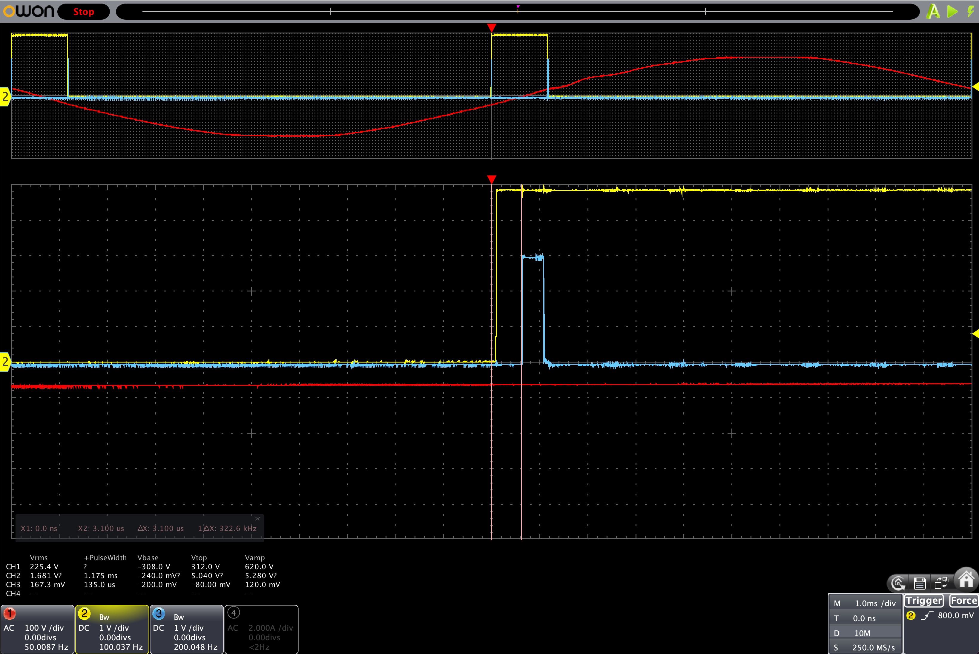
JSY-MK-194
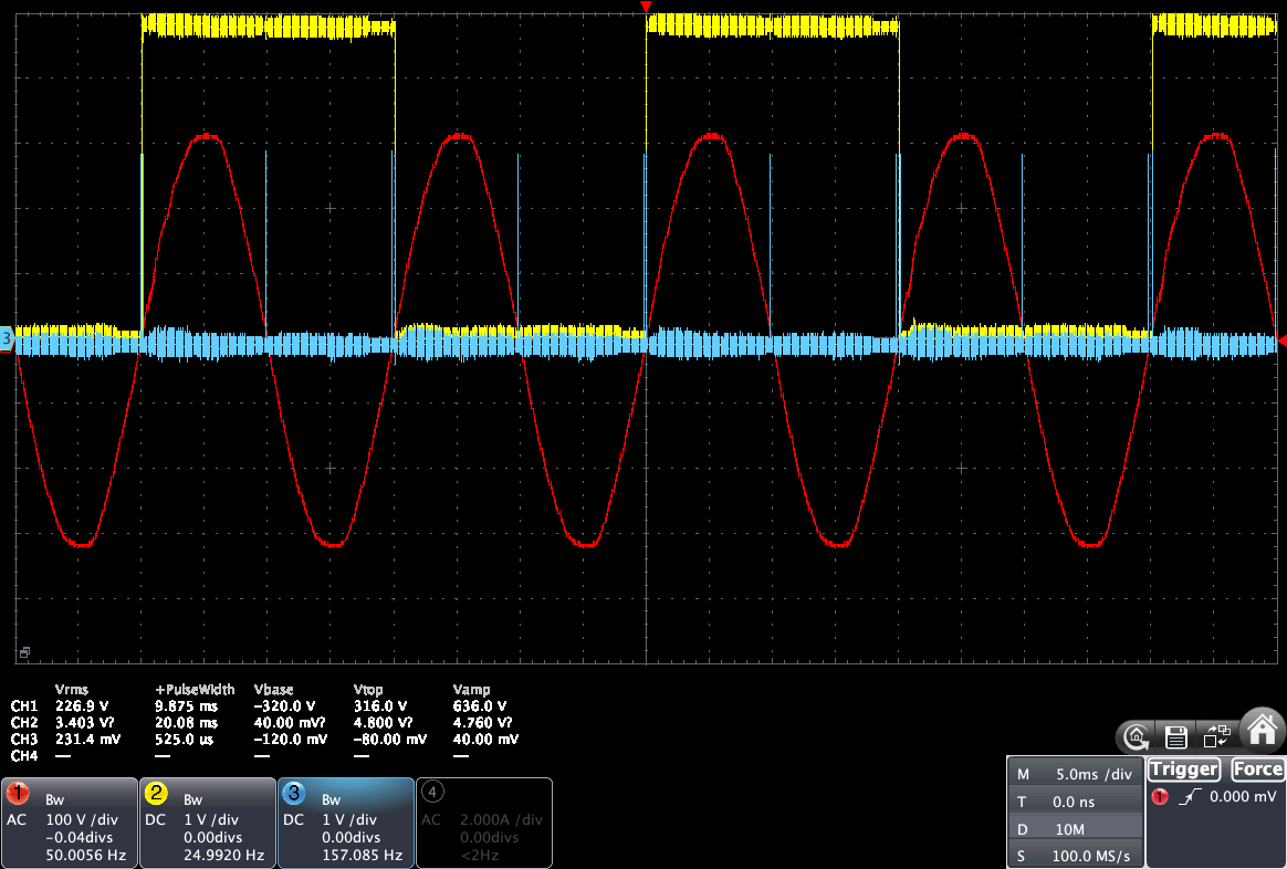
This library also supports the Zx pin of the JSY-MK-194G (JSY-MK-194T and other JSy boards probably supported, but untested), which is a ZC pulse of 20 ms.
View of the JSY-MK-194G Zero-Cross pulse on a 5 ms / div oscilloscope. The pulse width is 20 ms on a 50 Hz AC voltage.
View of the JSY-MK-194G Zero-Cross pulse on a 100 us / div oscilloscope. The blue lines represent the edge detection and the Zero-Cross event (shifted 100-150 us before zero).
You can also have a look at MycilaJSY to control the JSY-MK-194G.
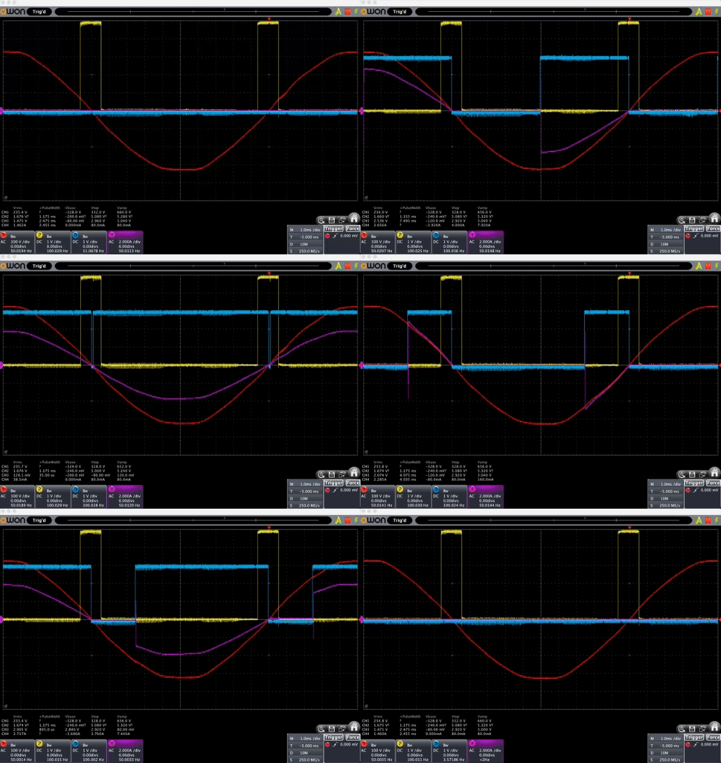
Use-Case: Thyristor TRIAC Control
You can look at the example in the project how to use this library to control a Thyristor / TRIAC with a zero-cross detection circuit.
- In yellow: the ZC pulse
- In blue: the output pin pulse of 1 us
- In red: main AC voltage
- In pink: current going to the load
Use-Case: Know when the AC voltage is positive or negative
The BM1Z102FJ has a positive pulse when the AC voltage is positive, and a negative pulse when the AC voltage is negative.
Thanks to MycilaPulseAnalyzer, you can know when the AC voltage is positive or negative by using the onEdge callback and check if it is a rising or falling edge.
Readings
Here is a blog post explaining how to use this library, with some oscilloscope screenshots:
https://yasolr.carbou.me/blog/2024-07-31_zero-cross_pulse_detection.

